SONY XDR-F1HD XDRF1HD TUNER MODIFICATION
I bought this little HD tuner at Amazon after reading the excellent reviews on the web. I have since sold it, after I bought an Internet Radio and get what I want that way.
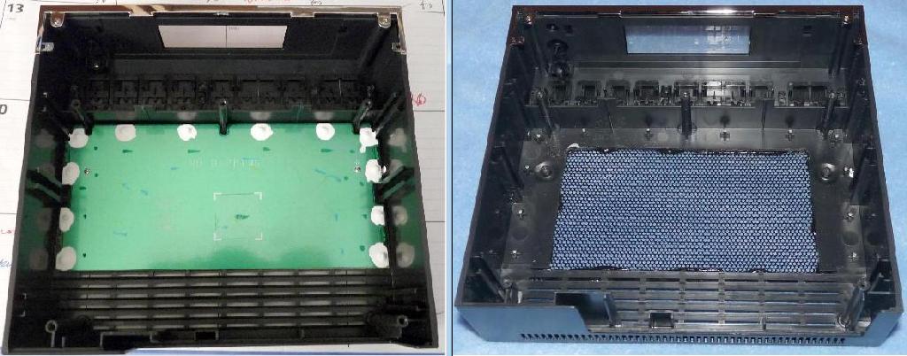
One thing that concerned me about this tuner is that it runs very hot. On the bench, with the top removed, I powered it up and as time goes by, the two modules (for the tuner and HD) start to heat up. The power supply transformer also gets warm. From the factory, Sony installed an unusual item in the top of the cabinet, a rectangular piece of metal coated with something. I think the idea was to act as a heat sink, and keep the heat from warming up the plastic case too much, and maybe protect whatever might be in the cabinet above it from excessive heat. One source said it got up to 145 F in there. What I did was remove the two little screws and pry out the Sony piece, and then cut out about a 3 x 5 section of the top of the cabinet and installed a black metal speaker grill I had from a small desktop speaker, which I cut to size, just slightly bigger than the cut out. I then put down a bead of black silicon and lay the grill on it and put a weight on it to hold it down for about 5 hours while it dried. You can see the before and after pictures here:
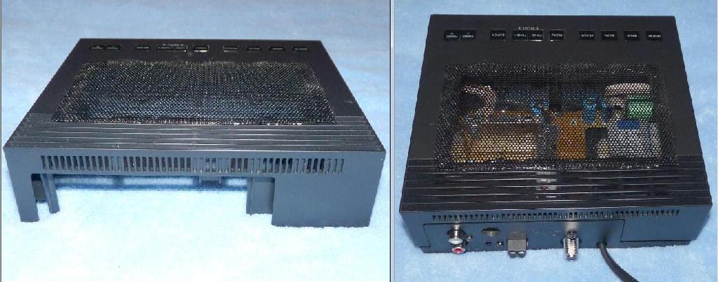
Here you can see how the new grill is directly over the modules and power supply, to let the heat escape. I also added four rubber feet to the top of the factory plastic feet, to increase the distance above the shelf and to provide more cooling air to come in the bottom.
I got parts from MCM Electronics in Ohio and my local Radio Shack store to complete the modifications I wanted to do. As seen in the following picture, I drilled a hole in the back and mounted a simple SPST switch and installed a 12 VDC Radio Shack cooling fan and wired it to the switch. It is Radio Shack catalog number 273-240 for about $13. I also drilled a hole in the back to mount a DC voltage input connector. So now, I hook up a 7.5 volt wall wart and switch it on and it powers the fan to cool and exit hot air from the module area that generates most of the heat. I mounted the fan using large solid copper wire to place it into the available area near the two modules. I drilled two holes in the rear of the case, and bent the wire to fit. Note the wire goes on top of the tab on the module. Don't want that copper to short out anything. Seems to work great. The copper wire holds the fan in place with no vibration, even if I input full 12 VDC to the fan. Running it at only 7.5 volt the fan runs slower and you can hardly hear it.
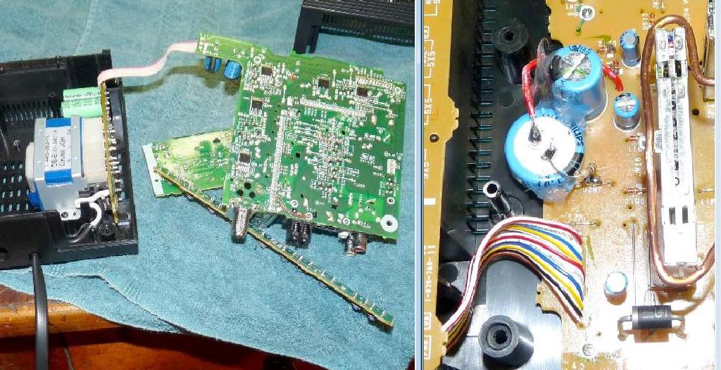
The other mod is I added a 1 Farad 5.5 volt capacitor in parallel with capacitor C926 and a 49 ohm resistor in series to ground to control the charging rate of the capacitor. This is as suggested on the web by Brian Beezley K6STI. So, now the tuner can be unplugged up to about one day, and it will still maintain the clock and preset memories. The capacitor is available at MCM Electronics, here is the info: http://www.mcmelectronics.com/product/31-0760 This is the best one I could find on the web, Brian said it must be at least 3.5 volts rating, this one is 5.5 volt rating.
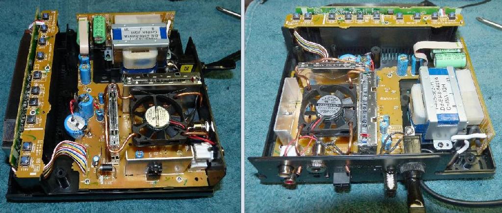
Here is a picture of the tuner all apart, as you have to get to the bottom of the main board to solder a wire from one side of the 1 Farad capacitor to the positive side of C926. The red wire I used can be run through the factory hole in the board and can be seen where I soldered it to a PCB foil that C926 positive side is soldered to. You can see that I used clear silicone to hold the new capacitor to C926 and a dab to hold it to the PCB. It is hard to tell from the picture, but the 1 Farad capacitor is very short and fat. The resistor goes from negative side of the 1 Farad capacitor to ground at jumper JW20. My thanks to Brian Beezley, and the other experts out there on the web that Google enables you to locate, for their advise on this tuner. I'm no expert, but have been in electronics since the tube days in the late 40's, and have the proper soldering and other gear. If you use common sense and due care, you can do this modification. The case comes apart easily, the screws to remove the main board are marked with little arrows, and same for the switch board and the display board. Always unplug all power prior to messing around with units like this. Pay attention when you take something like this apart, and make notes or take pictures with a digital camera, and lay out the screws where they won't get knocked and lost. Will make it a lot easier to reassemble it.
Any questions or suggestions are welcome. Email me at: marty AT duling DOT org